High quality noise in a FPGA – How the TKey TRNG works
Introduction
In a previous post about the Tkey random number generator app, we described how using the Blake2s hash function and an internal state could generate high-quality, cryptographically secure random numbers to support applications. In that post, we briefly said that the random number generator is periodically seeded using the True Random Number Generator (TRNG) core in the TKey. But what is a TRNG, what is its purpose, and how does it work? These are the questions we try to answer in this blog post.
TRNG – what it is and what it isn’t
A TRNG is something that is able to generate random numbers based on some sort of unpredictable behavior in a physical process. A process that can be measured. The unpredictable behavior is often referred to as entropy. In comparison to a random number algorithm, given a start value (a seed), which will always generate the same seemingly random sequence of values, the values from the measurement of the physical process are considered to be true random values. Hence the name, True Random Number Generator.
There are many physical processes that can be used as a source of entropy. Noise from a radio receiver, microphones, cosmic background radiation, and atomic decay are some examples. One of the more famous is the movement of bubbles in a lava lamp. Cloudflare famously uses this to secure the Internet.

No matter what type of physical process is used, they share some properties that determine how suitable a process is to be used as an entropy source for a TRNG:
- How hard is the source to integrate and use?
- Does the source require a lot of equipment or a specific environment to use and measure?
- How much entropy can the source provide?
- A single lava lamp changes slowly, and a radio receiver may provide many kilobits per second.
- What is the distribution of the entropy provided?
- Uniform, linear, or exponential in relation to some physical phenomena
- How hard is the source to manipulate?
- A lava lamp will become very stable if the source of heat is turned off.
- Noise from a radio can be drowned out with a stronger signal.
A good source of entropy is, of course, one that is easy to integrate into the target system, can provide a large amount of entropy, and cannot be manipulated.
The purpose of the TRNG is to collect entropy from a source, perform operations on the entropy data to improve the distribution, monitor the source for manipulation or breakdown and to provide the resulting random numbers to the rest of the system.
There are standards that describes how a TRNG should work and be monitored. For example, see the NIST document SP 800-90B and BSI AIS 20/31.
A TRNG normally provides random numbers with a capacity measured in kilobits per second (kbps). However, it may be susceptible to manipulation. Moreover, given one or a set of numbers, it does not offer cryptographic security against the guessing of previous or future values. In contrast, a Cryptographically Secure Pseudo-Random Number Generator (CSPRNG), such as the one described in the blog post about the TKey random number generator app, can provide Mbps of random numbers. It is difficult to manipulate and offers security guarantees against guessing attacks.
In general, one should never use the numbers provided by a TRNG directly in an application; instead, they should only be used to seed an algorithm—a PRNG, preferably a CSPRNG—that generates the necessary numbers. This applies even if there isn’t an obvious security aspect to how the numbers are used.
As a side note, all modern operating systems—from Android and iOS to Linux, Windows, and MacOS—contain random number generators. These can be used by both applications and the OS itself. These random generators are all based on a structure in which a TRNG, with one or more entropy sources, is used to seed and periodically reseed a CSPRNG. This CSPRNG then produces the random numbers for applications and the OS to consume.
The TRNG core
So, now that we have established what entropy sources are and what a TRNG is, let’s look at the TRNG in the TKey.
The TKey TRNG is one of the cores that make up the TKey System on Chip (SoC), implemented in a Lattice iCE40 FPGA. Unlike other designs, the TRNG is not connected to an entropy source outside of the FPGA. Instead, the entropy source is implemented inside the FPGA itself. Given that the FPGA is a digital device, how do we create a physical process that provides random, unpredictable patterns?
The source of entropy used is based on jitter between free-running digital oscillators. Let’s decipher that. A digital oscillator is a logic function where the output is fed back to itself as input, resulting in a sequence of ones and zeros. Normally, the function is an inverter; whatever bit is set as input, the output will be the inverse: 0 becomes 1, and 1 becomes 0.
If we had an inverter where the output was clocked into a register, and the output of the register was then used as the input to the inverter, we would get a sequence of alternating bits. However, this sequence would be very predictable. What we want is a digital oscillator running at an unknown and uncontrolled frequency—a single logic inverter that is connected to itself. Since it drives itself in a loop, this type of design is often called a ring oscillator.
Describing such a function in Verilog is actually a bit tricky. Normally, a synthesis tool would detect the combinational loop of the oscillator, making timing impossible to measure. The tool would also detect that the input to the inverter comes from itself, and nothing else, and would assume that the inverter could be optimized away. However, the synthesis tool used to build the TKey design supports specific instantiation and configuration of the logic blocks within the FPGA, allowing for the explicit setting of the logic function to be implemented by the logic block, and the connections of its inputs and outputs.
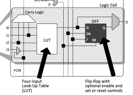
In the iCE40 FPGA device, logic functions are implemented using what is called a Logic Cell (LC). This figure shows the structure of a logic cell as depicted in the Lattice iCE40 UltraPlus Datasheet:

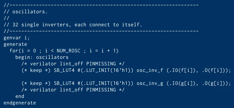
We can see that the LC contains a four-input Look-Up Table (LUT). Given the right bit mapping, the LUT can implement any four-input logic function, including a one-bit inverter. The output from the LUT can be sampled by the D-register within the LC. However, it can also be sent out of the LC unclocked. We want the output to go straight out and then be connected back to the LUT. So, we just need to explicitly instantiate a LUT and connect its output to one of its inputs. We can do this with the following code:

(This is the actual code used to implement the entropy source in the TRNG.)
The code essentially instantiates two arrays – osc_inv_f and osc_inv. Each array contains NUM_ROSC LUTs, each with input port zero connected to its output. The 16-bit LUT_INIT value configures the LUT to act as an inverter for the value entering on input port zero.
The frequency of a given oscillator is determined by the propagation delay through the LUT, as well as through the wires and switches on the FPGA die used to connect the LUT output back to its input. Essentially, this measures how quickly a zero generated by the LUT, configured as an inverter, can return and become a one by traversing through the logic of the LUT. In the datasheet, Lattice states that the maximum propagation through a LUT is nine nanoseconds (9 ns), but it can be much shorter. With some estimates on the propagation delay through the wires, the total propagation delay might be 10 ns, but is likely much lower. Essentially, each oscillator can be assumed to have a frequency of at least 100 MHz.
So, now we have two arrays of digital ring oscillators where the entropy comes from the slight difference in frequency due to the propagation delay, often called jitter.
From Entropy to Random Numbers
Sampling into bits
The oscillators are running at different, unknown frequencies, generating jitter-based entropy. But how do we use that to generate random numbers?
What we do is sample the outputs from the LUTs at a frequency much lower than their internal frequency. The CPU and the rest of the clocked digital design operate at 18 MHz. We use a counter running at 18 MHz to count 4096 cycles between samplings of the outputs — that results in a sampling frequency of 4.4 kHz. This approach allows the oscillators time to drift from each other, creating new jitter-based entropy.
The LUT outputs from each array are XOR-combined and stored in two registers. ‘XOR combined’ means performing the logical XOR operation between all inputs to produce a single bit. Essentially, if the number of input bits set to zero is even, the output bit will be zero
Time space conditioning
After sampling the bits, we want to further ensure that the bits are derived from collected entropy with low correlation between samples. Therefore, we repeat the sampling operation twice before generating data. This means that for each array, we obtain two bits. These two bits in each array are XORed together, and then we perform an XOR operation on the single-bit results from each array. We end up with a single bit that depends on entropy from two separate arrays of oscillators over two sample cycles. The final bitrate is about 2.2 kbps.
Random number generation
The resulting bits are shifted into a 32-bit register. When 32 bits have been shifted into the register, we set the status flag to indicate to the software running on the CPU that there is a new data word from the TRNG ready to be consumed. Note that the sampling and generation of random bits continuously run. This means that if the data word is not read out, it keeps being updated with new bits, ensuring the data word always contains the latest 32 bits.
When the data word is read, the status flag is cleared and remains low until 32 new bits have been shifted into the register.
Evaluation
So, with all these tasks being performed by the TRNG, how well does it work? There are a number of test suites that can be used. A common challenge is collecting enough data to perform meaningful tests. For example, the tool Dieharder often requires many tens of gigabytes of data. With a bitrate of 2.2 kHz, this becomes quite prohibitive.
A tool that provides a reasonable set of tests, yet is easy to use and yields fairly indicative results, is ENT (Pseudorandom Number Sequence Test Program). The results for 1.4 MBytes of data are shown in the figure below:

As can be seen, running a compression algorithm would not compress the file, meaning that the tool can’t find any repeating sequences. The mean value and variance indicate no bias, and there is no serial correlation. The estimated entropy is close to eight bits per byte.
This result does not prove that the TRNG is a perfect random number generator. However, it doesn’t have to be perfect—in terms of passing a large battery of tests—to be effective. The TRNG is sufficiently reliable for creating seeds for a cryptographically secure random number generator, such as the one implemented in the Tillitis RNG app.
Conclusions
In this post, we have described the purpose of true random number generators, how to generate entropy in a digital chip such as an FPGA device, and then how we use this to build our entropy source and generate random numbers from this entropy.
